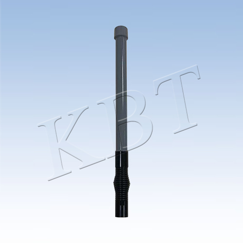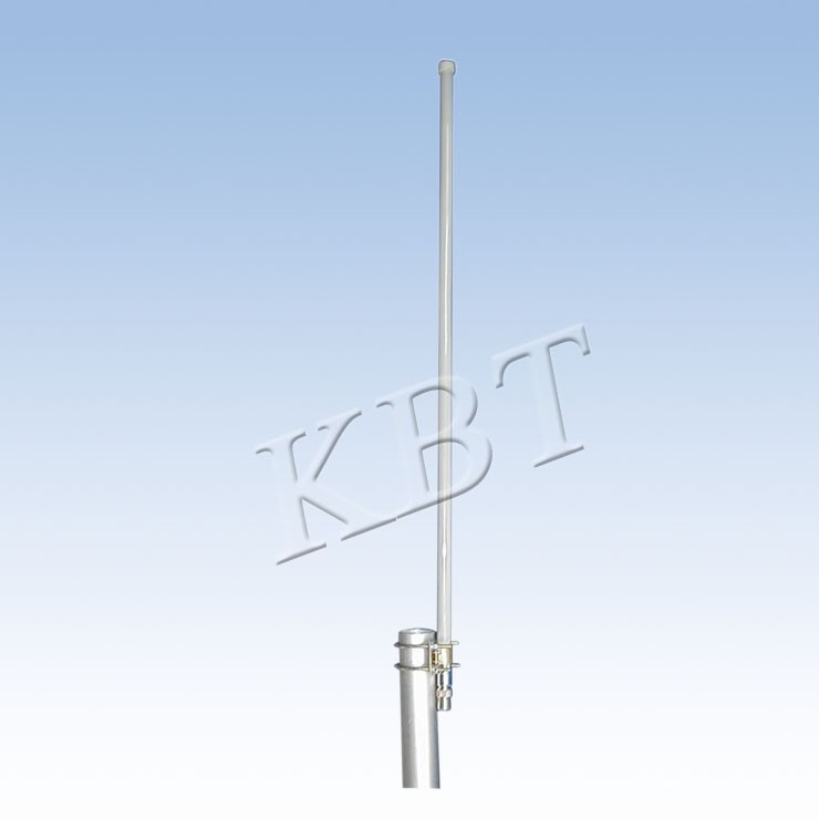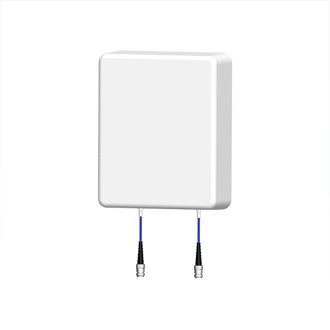

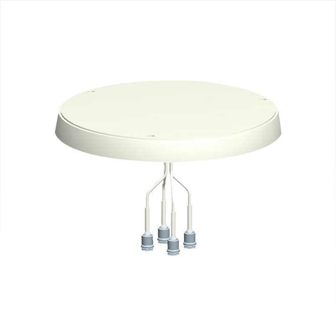
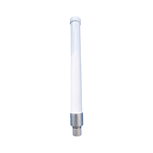
Electrical Specifications | Product Picture | ||||||
Frequency Range (MHz) | 2400-2500 | 5150-6000 | 6000-7125 |
| |||
Polarization | Vertical | ||||||
Typical Gain (dBi) | 5 | 7.5 | 7.5 | ||||
Horizontal Beam Width (°) | 360 | ||||||
Vertical Beam Width (°) | 35 | 16 | 13 | ||||
Impedance (Ω) | 50 | ||||||
VSWR | ≤2.0 | ||||||
Maximum Power (W) | 100 | ||||||
Lighting protection | DC ground | ||||||
Mechanical Specifications | |||||||
Connector | 1*N Male | ||||||
Connector Shell Material | Manufactured from brass, with a surface plating of copper–tin–zinc ternary alloy | ||||||
Connector Position | Bottom | ||||||
Base Shell Material | Aluminum material, with sandblasted and oxidized surface | ||||||
Radome Material | Radome:Fiberglass,Cap:ABS | ||||||
Radome Color | White or customized Gray,black, military green | ||||||
Radiator Material | PCB | Operating Temperature (°C) | -40 to +70 | ||||
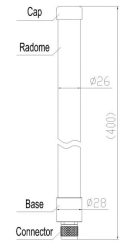
Antenna Size (mm) | Φ26*400(±5) | Storage Temperature range (℃) | -45 to +80 | ||||
Weight (g) | 180(±10) | Operating Humidity (%) | 5~95 | ||||
Ingress Protection | IP66 | Rated Wind Velocity (m/s) | 60 | ||||
Salt spray resistance | 96 hour neutral salt spray(GB/T 2423.17-2008) | ||||||
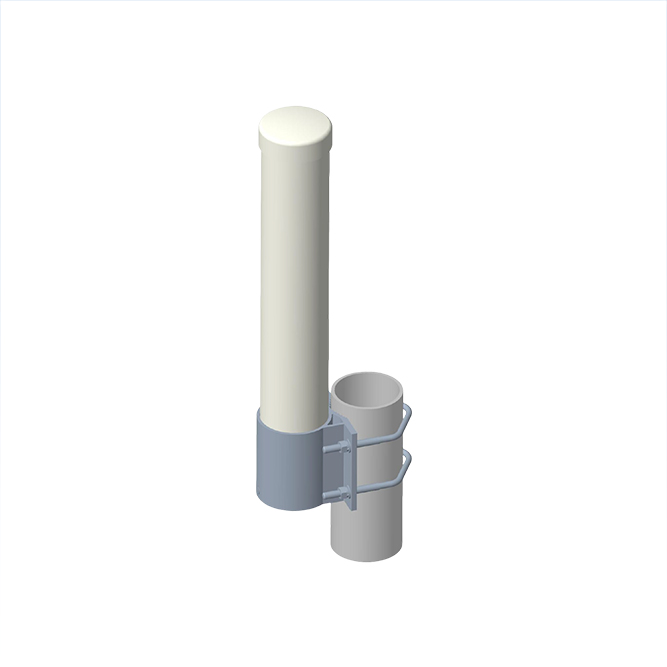
Mounting | Equipment installation | ||||||
Installation Sketch | Radiation pattern | ||||||
|
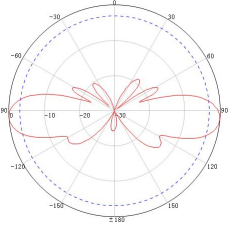
E plane |
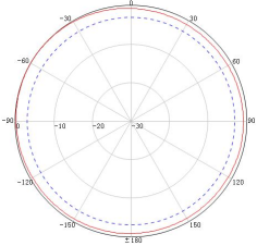
H plane | |||||